Products
Back to product overview
Download product sheet
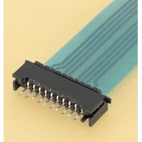
Side Entry Type THT Connector
Do you have any questions about this product?
More info on this brand:
 JST
JST
 JST
JST
Number Of Poles
- 5
- 6
- 8
- 9
- 10
- 11
- 12
- 13
- 17
| Article Number | 05FDZ-ST(S) |
| Number Of Contacts | 5 |
| Upper Temperature | +85 °C |
| Lower Temperature | -40 °C |
| General Description | 2.54mm Pitch ZIF Connector For FPC and membrane switch leads |
| Connection Type | Printed Circuit Board Connectors |
| Pitch / Style | 2.54 mm |
| Rated Current (ac/dc) | 1.0 A |
| Rated Voltage (ac/dc) | 250 V |
| Pcb Mount Style | Through-hole Technology (THT) |
Characteristics differ between variants of a connector
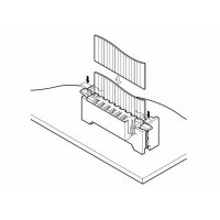
The FDZ connector, a Zero insertion force (ZIF) connector, was developed to connect FPC and membrane switch leads. This combination of features allows greater freedom in internal wiring designs. No force is required to insert the leads. Once inserted, the leads are securely held and locked by moving the slide. The contact is double-sided to ensure greater reliability.
Double-sided Contact
The contact is double-sided, thus providing redundant and highly reliable contact with FPC and membrane switch leads. this allows greater freedom in specifying the membrane switch lead conducting surfaces for use in keyboards.
Zero insertion force and locking mechanism
A ZIF mechanism increases wear resistance and extends the connector's mating life. The leads are securely connected by simply moving the slide. This greatly reduces the damage to the conducting surfaces of the leads. This mechanism is therefore ideal for silver-paste carbon-printed pattern leads which are suSCeptible to wear. The slide also has a hook to ensure secure contact and a tight hold.
Temporary board retention feature
The contact solder tail has a board retention feature that allows the connector to be temporarily held on the PC board while it is being soldered. As a result, the connector can be located accurately in the finished product.
Boss for polarity identification
A boss (projection) on the bottom of the housing prevents improper insertion in the printed circuit board and provides greater mounting stability.
Flux is not a problem
The bottom of the connector housing is raised 2.0mm (.079") from the surface of the printed circuit board. This prevents flux being trapped under the connector. In addition, the central section of the contact has a special form that prevents flux from rising into the connector due to the capillary action.
Caution: Flux level should be lower than the printed circuit board.
Standards
UL Recognized E60389
CSA Certified LR20812
RoHS Compliant


